| About Us | Gallery Search | About this Site | About Heavy Construction | |
|
|
| Home > The Bridge > | |
|
For the Extremely Curious: More on Design The following excerpt is from an article that first appeared in the Sept. 2000 edition of Civil Engineering magazine, a publication of the American Society of Civil Engineers. The authors are Man-Chung Tang, P.E., Rafael Manzanarez, P.E., Marwan Nader, P.E., Sajid Abbas, P.E., and George Baker, P.E.
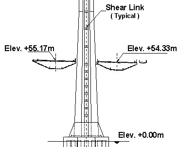
In the design, the 0.78 m diameter cable is anchored to the deck at the east bent and looped around the west bent through deviation saddles. Unlike traditional suspension bridge schemes, these deviation saddles are fixed to the west bent and the cable force on either side are balanced during construction using a jacking saddle. These saddles are supported by a prestressed cap beam that is designed to carry the differential stresses arising during service and seismic loads. The weight of this cap beam is designed to balance the dead load uplift at the west bent that results from the asymmetry of the bridge. The cables at the tower do not cross and are secured in a single saddle. The saddle at the east pier is supported by the box girders and is designed to move so that it can balance the cable forces on either side. The suspenders are splayed to the exterior sides of the box girders and are spaced 10 m apart. The superstructure consists of dual, hollow orthotropic steel boxes. These boxes are in compression (supporting the cable tension forces) and are a part of the gravity load system. Diaphragms spaced 5 m apart support the orthotropic deck and distribute the suspender loads to the box. The box girders are connected together by 10 m wide by 5.5 m deep crossbeams spaced 30 m apart. These crossbeams carry the transverse loads between the suspenders (at a span of 72 m) and ensure that the dual boxes act compositely during wind and seismic loads. The self-anchored suspension bridge consists of a 385 m main span and a 180 m back span. The tower will be 160 m tall and will comprise four steel shafts connected with intermittent steel shear links along its height. The eccentric load caused by the pedestrian path on the south side is balanced by a counterweight on the north side. At the west bent, the box girders frame into the cap beam, which serves as the box girder at that location. The connection between the orthotropic steel box girders and the concrete cap beam is subjected to the compressive forces of the cables. Additional prestress is added through looped posttension strands connected at each rib to ensure that the steel box yields before the connection fails. The east piers are reinforced-concrete columns with added prestressing to avoid shear failure in tension when subjected to seismic loading. They are supported on 16 steel shell pipe piles 2.5 m in diameter. These piles are 100 m long and are filled with earth up to 55 m from the top; the rest is filled with concrete. The west piers are reinforced-concrete columns enclosed by a steel shell to improve ductility. The columns are made monolithic with the prestressed cap beam, forming the west bent, and are supported on rock through a 12.5 m deep gravity footing. At the west pier, a tie-down system, designed to resist a seismic uplift, consists of 28 stay cables, each with 61 strands 15 mm in diameter. The stay cables are anchored into the footing. At the east piers, the box girders are supported on bearings. Shear keys and tie rods are provided to carry lateral loads and uplifts, respectively. The box girders are supported at the east and the west pier for lateral loads and are "floating" at the tower.
Balanced-cantilever cast-in-place (CIP) and precast segmental construction erection is being evaluated for the skyway. Concrete of normal weight will be used for the superstructure except for the side inclined panel or webs, where lightweight concrete will be used. The 28-day concrete strength for both the lightweight and normal-weight concrete is 50 MPa. The box girder is a single cell with two main vertical webs. The width at the bottom slab, or soffit, is 8.5 m, a dimension that is optimum from the seismic standpoint of pier column design. The 25 m width accommodates deck overhangs of 8.3 m on each side. Inclined girder panels or webs posttensioned both longitudinally and transversely were considered the most effective design to carry the eccentric bike path loading. Vertical posttensioning is used to control the shear stresses in the main webs of the girder. The 160 m spans are arranged in frame units of three or four piers per frame with a girder depth of 5.5 m at the midspan and 9 m at the pier. Midspan hinges between the frames allow longitudinal expansion and contraction caused by creep, shrinkage, and temperature changes. An internal steel beam assembly at the hinge provides shear transfer and moment resistance in addition to controlling deflections at the cantilever end of each frame. These beams are rigidly connected to the box girder at one end and slide on bearings at the box girder at the other end of the cantilever.
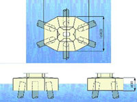
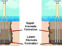
The piers of the skyway are about 50 m in height and stand in water depths of 15 m. This, added to the presence of a 15 m layer of young bay mud, establishes a very flexible structure. The design approach for such piers was to adopt a stiff foundation system, thereby confining the elastic displacements of the pile caps to acceptable levels and minimizing the potential for permanent offsets. A relatively stiff foundation system for the tall, flexible piers was achieved by using large-diameter battered steel piles filled with concrete. The thickness of the pile shells was determined by the required flexural capacity of the pile, the ductility capacity of the pile, corrosion allowances, and drivability. In particular, the flexural demands governed the thickness at the upper regions of the piles, and drivability governed the thickness in the lower regions of the shells. The thicknesses ranged from 40 to 70 mm. To ensure the proper transfer of loads from the concrete fill to the steel shell, shear ring plates will be welded to the inside of the steel shell in the concrete-filled section.
The YBI transition structures are technically and logistically challenging because of the roadway geometry, the positioning of future on- and off-ramps, the island's topography, structures of historical importance, and temporary detours. The eastbound and westbound transition structures connect the main-span structure to the existing viaduct section near the Yerba Buena tunnel's east portal. The two structures are carried on separate single-column bents, except near the viaduct end, where they are supported on outrigger bents. The separate transition structures currently merge into the existing double-deck viaduct structure. The length of each transition structure is approximately 467 m. The westbound structure has an overall deck width of 25 m and varies in depth from 1.6 m at the viaduct end to 4.5 m at the main-span hinge support. The height of both structures varies from 8 m at the viaduct end to 46 m above grade at the main-span end. Most bents are located in overburden sand and are supported on cast-in-drilled-hole piles. The superstructure of the transition structures consists of cast-in-place reinforced-concrete box girders near the outrigger bents and cast-in-place prestressed-concrete box girders over the single-column bents. The shape of the box girders has been determined primarily by aesthetics to match the streamlined girder shape of the main-span superstructure and skyway. The Oakland shore approach presented its own set of challenges. The westbound structure extends from the tip of the Oakland Mole to the point where the proposed westbound Route 80 joins the existing Route 80, connecting the Oakland shore to the skyway. The total length of the westbound approach structure is about 660 m, which is subdivided into two sections, an elevated structure and one that is essentially at grade. The eastbound approach structure is an elevated two-span frame 105 m long. The eastbound structure and the westerly portion of the structure are elevated and consist of a cast-in-place, prestressed-concrete box girder superstructure supported on reinforced-concrete piers, reinforced- concrete footings, and prestressed-concrete piles or small-diameter pipe piles. For the westbound at-grade structure, a flat-slab-on-piles option was selected. Man-Chung Tang, Ph.D., P.E., is the chairman of the board of T.Y. Lin International, San Francisco. Rafael Manzanarez, PE, is a vice president at T.Y. Lin, and Marwan Nader, Ph.D., PE, and Sajid Abbas, Ph.D., PE, are both principals of the company. George Baker, PE, is a senior engineer at Weidlinger Associates, Inc., in New York City. -- Reprinted with permission of the American Society of Civil Engineers |
||||||
|
|